FAQs
- What are the Status Error Codes and Remedy for my Fronius Wattpilot EV Charger?
Status codes and remedy on Fronius Wattpilot EV Charger
Due to phase, voltage and switching function checks of the Fronius Wattpilot, a charging operation may be rejected.
The status codes are displayed via the LED status indicator (see LED status indicator on page 17) directly on the Wattpilot and in the app under "Status".
Status Codes
Issue Cause Remedy 1
Fault current detected (LEDs light up pink, the LEDs at the top flash red)
The residual current device has detected an error. The charging equipment in the vehicle may be defective. Have the charging equipment checked by a specialist. Disconnect and reconnect the charging cable. 3
At least one phase of the power supply is missing (the LEDs light up blue, the LEDs at the top flash red)
The device is only being supplied with 2 phases. Make sure that phase 2 and phase 3 are connected correctly. Option: a supply via phase 1 only is possible. 8
Grounding fault detected (the LEDs light up green and yellow, the LEDs at the top flash red)
Grounding fault detected. Check that the connection is properly grounded. 10
Relay fault detected
The relay has not switched. Disconnect the power supply to the device for 5 seconds. 11
Backup power mode detected
53 Hz mains current detected. Observe the instructions in the Operating Instructions. 12
Type 2 plug locking failed
The plug locking system does not work. Remove possible foreign parts in the plug housing. Type 2 plug not fully inserted. Insert the type 2 plug into the device as far as it will go until you hear a click. 13
Type 2 plug unlocking failed
The electric vehicle is plugged in. Unplug the electric vehicle. "Always locked" under "Cable release" in the Solar.wattpilot app is activated. Deactivate "Always locked" under "Cable release" in the Solar.wattpilot app. Release jammed. Insert the type 2 plug into the device as far as it will go until you hear a click. If the problem has still not been fixed: Press the push button on the device. If the problem has still not been fixed: Activate and save "Always locked" in the Solar.wattpilot app, then activate and save "Standard mode" under "Cable release". 100
Internal communication error (all LEDs flash red)
Device is not sending data. Disconnect and reconnect device. Perform a firmware update. Return device. 101
Temperature too high (the LEDs light up yellow, the LEDs at the top flash red)
Continuous load. Disconnect device and allow to cool down. Incorrectly installed cables. Disconnect device and allow to cool down. 105
No data available on the flexible electricity tariff (first or second LED - Eco Mode or Next Trip Mode - flashes red)
Flexible electricity tariff cannot be called up. Check WLAN and Internet connection. Wait until the server is available again. 109
No connection to the inverter (first or second LED - Eco Mode or Next Trip Mode - flashes red)
The connection to the inverter cannot be established. Check the network settings. Check the settings of the inverter. 114
For Eco Mode, PV surplus or flexible electricity tariff must be activated (Eco Mode LED flashes orange)
Eco Mode is selected and the "Use PV surplus" and "Use Lumina Strom / aWattar" settings are disabled. Activate the setting "Use PV surplus" and/or "Use Lumina Strom / aWattar". Change the mode. "Use Lumina Strom / aWattar" is enabled and there is no data connection to the Internet. Cached price data is still available. Check the network settings. 115
The set amount of energy cannot be reached in the specified time (second LED - Next Trip Mode - flashes orange)
The specified time is not sufficient for the desired amount of energy. Extend the specified time for charging. Reduce the desired amount of energy. 116
Update of flexible electricity tariffs failed (first or second LED - Eco Mode or Next Trip Mode - flashes orange)
The connection cannot be established. Check the network settings. The charging operation cannot be started, but all LEDs show the ready colour (default blue).
The vehicle is not being detected. Check vehicle cable and fit of charging plugs No LEDs light up after plugging in.
No power on the junction box. Check the overload fuse of the connection. Miniature fuse defective. Check the miniature fuse on the rear of the device. If it has melted, the power connection may not be installed properly. Check the polarity of the power connection before starting another test with a new miniature fuse. Use original miniature fuses only. The brightness of the LEDs has been set to 0. Increase the brightness of the LEDs in the Fronius Solar.wattpilot app. "Switch off LEDs after 10 s in standby" has been enabled. Deactivate "Switch off LEDs after 10 s in standby" or press the push button on the Wattpilot. - Correct Usage of Tesla Powerwall 3 Expansion Harness
How to Correctly Connect and Install Your Tesla Powerwall 3 Expansion Units
If you are expanding your Tesla Powerwall 3 system, it is important to understand how to properly use the Powerwall 3 Expansion Harness. This guide answers common questions about connection, configuration, and safe installation for Powerwall 3 Expansion Units.
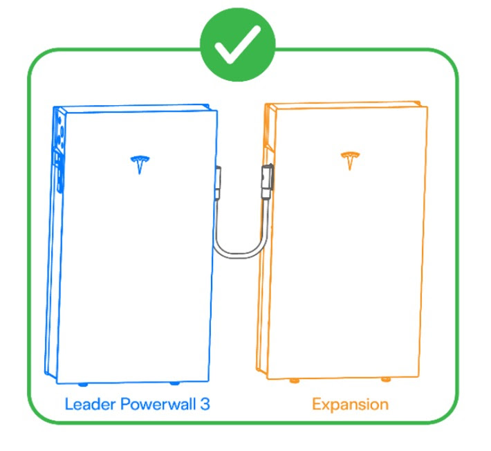
What is the Powerwall 3 Expansion Harness used for?
The Powerwall 3 Expansion Harness is an essential component in Tesla Powerwall 3 installations. It allows Powerwall 3 Expansion Units to connect securely to either the Leader Powerwall 3 or other Expansion Units within the system. The harness enables safe power and data communication between connected units, ensuring reliable performance and energy management.
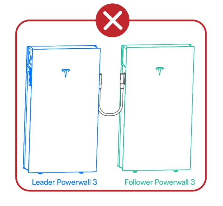
Can I use the Expansion Harness to connect two Powerwall 3 units?
No. The Expansion Harness should not be used to connect a Leader Powerwall 3 to a Follower Powerwall 3. Follower units must connect to the Leader Powerwall 3 and other Followers using Ethernet cables. This ensures proper communication and safe operation within the Powerwall system.
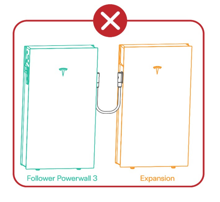
Can a Follower Powerwall 3 be connected to an Expansion Unit using the Expansion Harness?
No. Expansion Units can only be connected to a Leader Powerwall 3, not to a Follower unit. Connecting a Follower to an Expansion Unit using the Expansion Harness may cause system faults and compromise safety compliance.
What is the correct setup for multiple Powerwall 3 and Expansion Units?
To ensure a safe and compliant installation:
Connect Expansion Units only to the Leader Powerwall 3 or other Expansion Units.
Connect Follower Powerwall 3 units to the Leader Powerwall 3 using Ethernet connections.
Follow Tesla’s installation guidelines and local building or electrical codes to ensure compliance.
This setup supports efficient communication, dependable backup power, and optimal performance for your Powerwall 3 system.
- How to set up monitoring for my Fronius Wattpilot EV charger?
The Fronius Solar.wattpilot app can be used to start up, configure, operate, visualise and update the Wattpilot. The app is available for Android™ and iOS®.
Download The Fronius Solar.wattpilot app is available on the following platforms.
You can access the Wattpilot via the app as follows:
Launching the app
- Open the Fronius Solar.wattpilot app on the end device and follow the Setup wizard.
- Read and accept the terms of use
- Click on "Connect"
NOTE: Access for the Fronius Solar.wattpilot app must be allowed for end devices with an iOS operating system.
iOS settings > Privacy > Local network > Fronius Solar.wattpilot > Allow access to local networkSetting up a hot spot
The Wattpilot permanently opens a hot spot
- Scan the QR code on the reset card or connecdt the end device to the WLAN hot spot. The passowrd is located on the reset card of the Wattpilot.
- Follow the further instructions in the app.
NOTE: The selected WLAN of the Wattpilot must remain connected despite the absence of an Internet connection for end devices with an Android operating system.
Setting up the WLAN
- Select WLAN and enter the password
- Follow the further instuctions in the app.
NOTE: It can take up to 1 minute to establish the connection! If the signal strength is low, a WLAN repeater must be installed, for example.
Adding a Wattpilot
New or connected Wattpilot devices can be added in the Fronius Solar.wattpilot app.
- Click on the "+" symbol
- Click on the "Add" for the connected Wattpilot
- Follow the further instructions in the app
- Why does the Sanden Eco® Plus use CO2 as its working gas? Isn’t CO2 a greenhouse gas and therefore harmful to the environment?
Why does the Sanden use CO2 as its working gas, what is the benefit?
- There is far less environmental impact (i.e. No ozone layer depletion and minimal global warming) than other commonly used refrigerants, should the system leak.
- There is a much higher efficiency, thereby allowing more heat to be transferred to the water, for less energy used (i.e. Excellent thermodynamic ability).
Isn't CO2 a greenhouse gas and therefor bad for the environment?
While it is true that Carbon Dioxide (CO2) is a greenhouse gas it has a Global Warming Potential (GWP) of 1. Whereas refrigerant gases in other heat pumps can have GWP of over 10,000, which means if they leak to the atmosphere they contribute 10,000 times more to global warming compared with the refrigerant gases used in a Sanden Eco Plus.
The table below shows the GWP for some common refrigerant gases (note: GWP must include a time interval over which the greenhouse gases act, in this case 100 years)
Our system utilizes less than 1 kg of R744 (CO2) as a refrigerant contained in a closed system at the factory. The installer does not need to charge the heat pump on site.
- There is far less environmental impact (i.e. No ozone layer depletion and minimal global warming) than other commonly used refrigerants, should the system leak.
- Do I need to register my Sanden Eco Plus warranty?
- Uploading Photos for Sanden Eco Heat Pump Quote
Uploading Photos for Sanden Eco Heat Pump Quote
As heat pump hot water systems receive Government subsidies and rebates, Government authorities are requiring all photos are GEO-tagged to comply.
If you are unsure that your photos are GEO-tagged, we have a helpful Geo-tag guide on our website here -> https://pure-electric.com.au/resources/geo-tagging-helpful-guide
You can test if your photos are GEO-tagged by uploading photos to this website -> https://tool.geoimgr.com/
Please see below some photo tip examples for uploading photos to your Sanden Eco heat pump quote request.
Existing Hot Water System (Left)
Photo Tips: 2-3m to the left of the tank and up to the eaves
Existing Hot Water System (Right)
Photo Tips: 2-3m to the right of the tank and up to the eaves
Existing Hot Water System (Serial Number)
Photo Tips: Clear and readable
Switchboard
Photo Tips: Clear and readable so if you zoom in you can see the circuit breaker rating, enclosure flaps are open
Meterbox (Outline)
Photo Tips: Meterbox Door Open
Old Tank Details (Example filled in:)
Old Tank Make: Rheem
Old Tank Model: 315T136G
Old Tank Serial: 33633XXXX
Old Tank Date: 15/03/2006
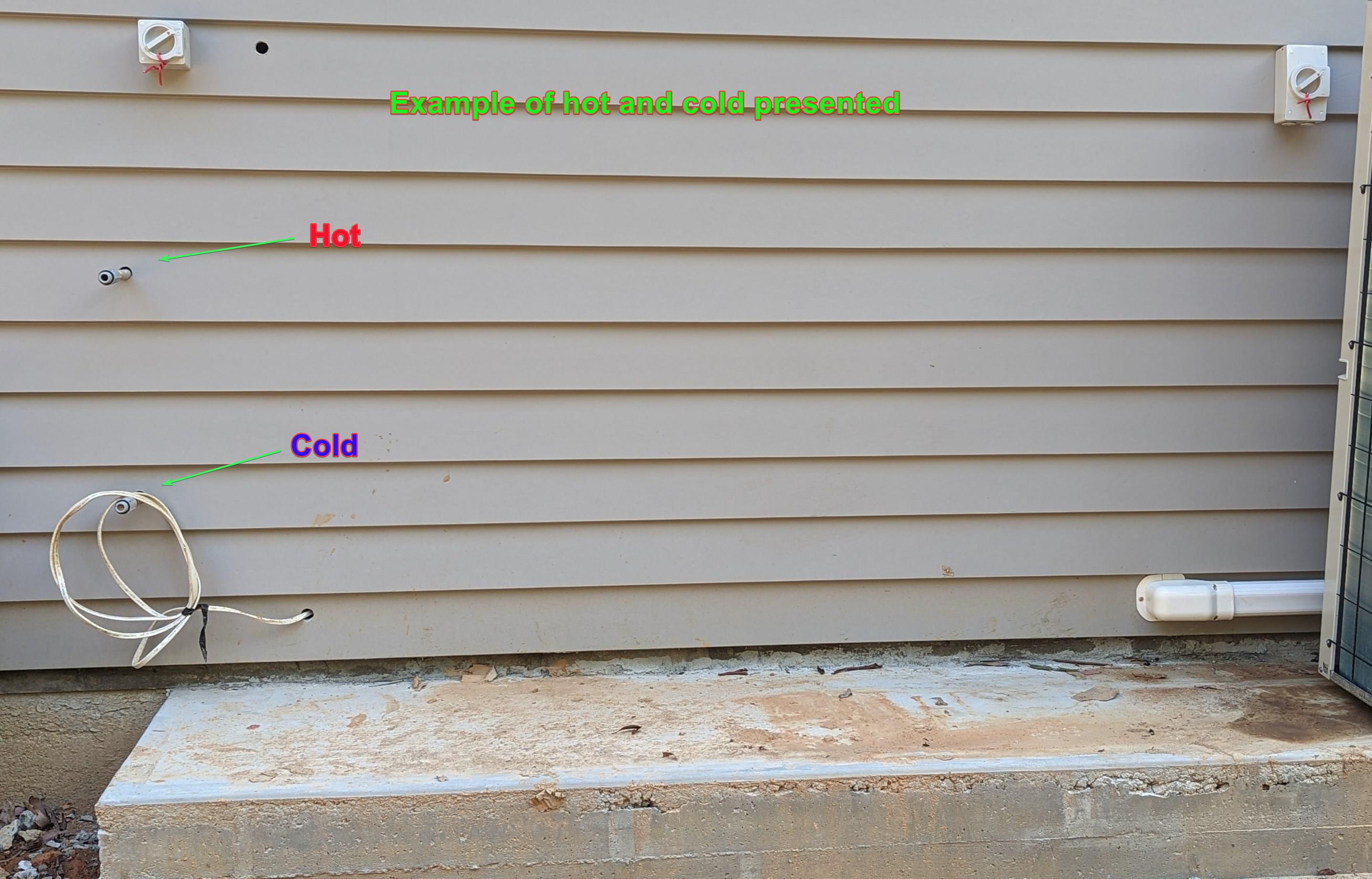
If you have a renovation with a new hot water system location, please share a photo that confirms both hot and cold connections are presented:
- What is the noise level of the Sanden Eco® Plus heat pump hot water system?
The unit is rated at 37dB (measured at one metre from the unit), which is almost silent. By comparison, a whisper is around 30dB and the sound of the inside of a Library is approximately 40dB.
- Sanden Eco Hot Water Tank Size Options? Which tank size should I choose?
The Sanden Eco Plus hot heat pump hot water system is available in the following five sizes with our sizing guide below:
Tank size/shape Tank Code System No. of People No. of Bathrooms Dwelling type Off-peak & Continuous tariffs? Tank Diameter (mm) Tank Height (mm) 160L SS SAN-160SAQA GAUS-160FQTS 1 1 Bedsits Continuous only 621 970 250L SS
SAN-250SAQA GAUS-250FQTD 1-3 1-2 Residential Both 621 1428 250L SS Tall Slim SAN-250SAQD GAUS-250FQTD 1-3 1-2 Residential Both 580 1635 300L SS Tall Slim SAN-300SAQA GAUS-300FQTS 2-6 1-3 Residential Both 580 1891 300L SS Tall Slim SAN-300SAQD GAUS-300FQTD 2-6 1-3 Residential Both 580 1905 315L SS SAN-315SAQA GAUS-315FQTS 2-6 1-3 Residential Both 621 1748 315L SS Tall Slim SAN-315SAQD GAUS-315FQTD 2-6 1-3 Residential Both 580 2000 315L VE SAN-315VE GAUS-315FQTV 2-6 1-3 Residential Both 638 1626 *SS = Stainless Steel // VE = Vitreous Enamel
The same Sanden Heat Pump condenser unit is used in combination with different tanks sizes. So which tank size you would like?
When considering tank sizes - we need to consider a few factors - number of people, number of bathrooms, the heat recovery rate.
If you're using an existing hot water system for comparison - here are some comments/thoughts:
If you have an existing gas storage hot water system (e.g. 130L / 170L) - these are much smaller in capacity but they will reheat several times a day. Therefore the Sanden tank size will be larger than an existing gas storage replacement with the Sanden re-heat typically only required once per day - a good opportunity to maximise rooftop solar PV production or to utilise an off peak tariff.
If you have an existing electric storage hot water system (e.g. 400L 3.6kW unit) - these electric storage 3.6kW units recover heat at a slower rate (60L/hr) compared to a Sanden heat pump (approx. 80L/hr). Therefore a 400L electric storage hot water system would equate to a 300L/315L Sanden system in this example.
Based on our years providing the Sanden Eco heat pump hot water system - here are our tank recommendations for different scenarios (SS - Stainless Steel // VE - Vitreous Enamel):
160L SS: Only recommended for 1 person bedsits. This tank size is rarely chosen and due to its small tank size must be run in Continuous only mode (no blockout timer can be set up).
250L SS: Typically 1-3 person household with 1 bathroom. Height just under 1.5m with tank diameter 621mm.
250L SS Tall Slim: Typically 1-3 person household with 1 bathroom. Height just under 1.635m with tank diameter 580mm.
300L SS: The Tall Slim - the most popular and best recommended tank choice. Recommended for 2-6 people. Tank diameter 580mm and tank height just under 1.9m. If no height restrictions apply, this is the recommended tank for majority of situations and considered best value for money across the tank sizes.
315L SS: The largest tank size with an additional 15L delivered hot water (5% more) compared to the 300L Tall Slim tank. Tank diameter 621mm with tank height 1.74m - this is recommended if the 300L tall slim tank is too tall for your application.
315L SS Tall Slim: The largest tank size with an additional 15L delivered hot water (5% more) compared to the 300L. Tank diameter 580mm with tank height 2m - this is recommended if you're a very high hot water user.
315L VE: Tank diameter 638mm with tank height 1.63m with 315L delivered hot water. This VE tank is specified for poor water quality areas - you can identify if you are in a poor water quality area via the Sanden website -> https://www.sanden-hot-water.com.au/check-water-quality/
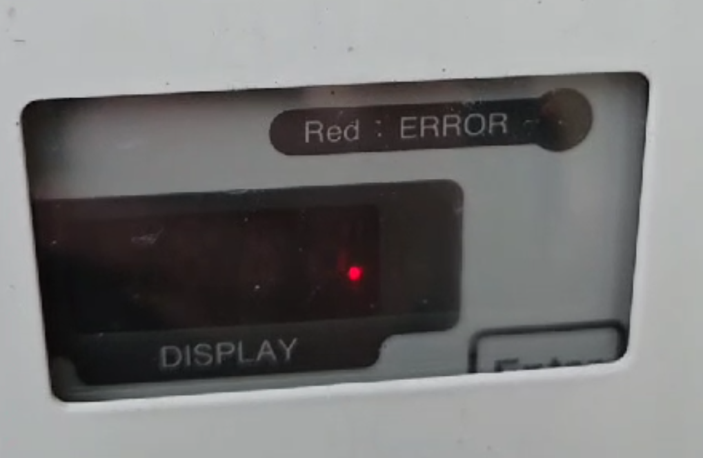
- There is a red LED flashing on the Sanden heat pump display panel should I be worried?
The flashing red dot (LED) indicates the Sanden heat pump unit is currently in 'sleep mode', it is perfectly normal and nothing to worry about.
We consider this the "Sanden Heart Beat". If you see a red flashing dot, the heart is beating and all is well for your Sanden heat pump.
This controller display with the red flashing dot is applicable to the following Sanden heat pump models:
Sanden G3 - "GS3-45HPA-AU"
Sanden G4 - "GAU-A45HPC"
Sanden G5 - "GAU-A45HPD"
- At what temperatures will the Sanden Eco® Plus heat pump hot water system operate effectively?
The Sanden Eco Plus heat pump hot water (HPHW) system will operate effectively between - 10 º C and + 43 ° C, without the need for an electric booster element. It is also fitted with built in freeze protection, making it suitable for all climates.