FAQs
- The cold water valve (or ECV) on my Sanden is leaking a lot what is causing this?
To answer the question why is my cold water valve (or ECV) on my Sanden leaking a lot what is causing this? A few elements to consider.
To protect your Sanden unit from excessive pressure there are three valves:
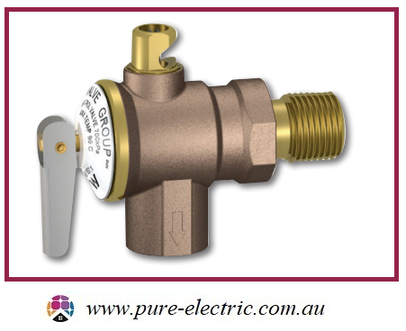
Valve 1. The pressure reduction valve (PRV) which is located on the water inlet to your home and is set to 500kPa. This valve is designed to keep the pressure out of any tap in your house below 500 kPa.
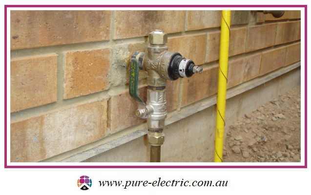
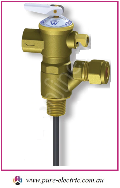
Valve 2. The expansion control valve (ECV) which is located on the cold water inlet to your Sanden and is set to 600 kPa. This valve is designed to relieve cold water instead of hot water during the heating cycle (which increases pressure in the tank) which saves you money and protects the final valve, the PTR.
Valve 3. The Pressure and temperature relief valve (PTR) which is located on the hot water outlet to the Sanden and is set to 700 kPa. This valve is designed to release hot water from your tank if the pressure gets too high or the water heating cut-off fails to work.
One of the main reasons ECV valves leak water excessively (apart from wear and tear or malfunction) is excessive water pressure in the mains supply which is not properly being reduced by a PRV as it enters your house to at or below 500 kPa; in many areas the mains water pressure is 850 kPa + this is to ensure fire fighters have enough pressure to use their fire hoses properly in the event of a fire.
Note: the Australian standard covering water pressure in the home (AS 3500.1:2018) mandates that water pressure in your home must be kept below 500 kPa as water pressure above 500 kPa has the potential to damage valves, tap fittings, flexible hose fitting etc as the components are only rated to withstand pressures at or below 500 kPa.
So if you notice that the expansion control valve (valve 2 discussed earlier) on your Sanden is leaking excessively chances are you have excessive water pressure at your house and your PRV (valve 1) is either not present or not working.
Either way you should get a plumber to check the water pressure in your house and make sure you have a functional PRV. You can also buy a cheap pressure meter from a hardware shop if you want to check your household water pressure yourself: Note your mains pressure is not constant it will change based on a number of factors including local water use, time of day, time of year or changes in your local area such as new housing being built etc.
- Sanden Heat Pump Hot Water Not Working
If you believe your Sanden Eco Heat Pump is not producing hot water, please try the following:
- Unless there is water pouring (not dripping) out of the unit, do not turn the unit off and on until you've checked the clock / control panel for an error message (under our "Resources" section you can find the different error code pages to help you determine what an error code looks like). If water is pouring out then turn the unit off at the isolator and at the switchboard that circuit is attached to.
- Pull the PTR Valve on the Tank - this confirms if there is hot water in the tank. If unsure about the water temperature use a thermometer. If water is cold goto (2) If there is 50C or so hot water in the tank then the problem is not the heat pump system) the problem is on the house side of the tank. So the tempering valve needs to be checked for a blockage / choke, if it is installed upside down or if it has failed (they are consumable items with a lifespan of 5-6 years and they fail to safe when they fail meaning cold water).
- Check the electricity supply - Confirm/check both (1) circuit breaker at the switchboard is ON + (2) Isolator at the HP unit is ON
- If you see a little Red Dot in the bottom right corner, then the HP unit has power connected. For the older G2 model 2010-2016 the dot is on the controller hidden under the lid - you will need a screwdriver to remove the 4 screws from the each end of the lid.
- Check if there are any Error Codes at the clock/computer control panel. If an error code is present, take note of the Error Code. Turn off the HP at the isolator (wait 1 minute) and turn on the HP again to see if the Error Code re-appears. The unit is functioning correctly if it blows cold air for more than 30minutes. NOTE: The unit takes about 7 minutes to start blowing cold air after power is applied.
- If system is newly installed or new plumbing works have occurred on site confirm that the tempering safety valve (valve with orange/yellow cap) is installed the right way up with a H on the vertical barrel above the adjustable valve and a C below the adjustable valve. If the system is more than 5 years old please note these valves officially only have a minimum life span of 5 years and may need replacing.
- Air bleed the system - Open the water drain plugs on the right hand side of the HP unit (one at a time for a good 3 minutes PER drain plug, ONE at a time). G4 units have an additional bleed port on the underside of the heat pump - please only turn this 180 degrees approx when opening it up - bleed this for 3 minutes also. Re-set the HP unit at the Isolator.
- Hard re-set the HP unit controller:
- Switch off power to the HP
- With power switched off press and hold down both “Up” and “Down” keys on the control panel simultaneously
- With the keys still pressed switch on power to the unit, the display will show “FClr” .... wait 10 seconds.
- To complete the reset cycle power to the unit off (wait 1 minute) and then on again.
- With power back on the time will be displayed (if required adjust to correct time) and the unit will run it's start up procedure.
- When switching power on again, the country setting "1.AU" may appear on the display. If for any reasons this setting remains on the display, simply press "Enter" and the Control Panel to confirm and HP will continue the start-up process.
- Physical inspection of the HP
- Turn off the electrical isolator, to allow power to discharge, wait 5 minutes after the power is turned off
- Take the top panel off by unscrewing the 4x screws
- Check to see if any debris/foreign objects are the top of the unit
- If an onsite plumber or electrician has a volt meter check for ~230VAC at the terminals on the side of the unit.
- If you have an older G2 unit and E124 is displaying then the unit has been subject to either high grid voltages or has suffered a power spike. Adding a timer to the switchboard and keeping the unit powered off for more than 19 hours per day can clear the fault for each and every use. This is successful in 50% of cases however works better where it is done the first time the error is ever seen. Not where the unit has been turned on and off many times.
- If you are getting E040 on an older G2 unit then you can clean the filter via the filter housing at the bottom of the unit adjacent the air bleed drain plugs. This may get you up and running again temporarily while you book a service. BOOK YOUR SERVICE OPTION HERE
- For blockages in newer units a 3 way ball valve can be installed which allows the consumer to perform their own reverse flush of the system. This maintenance step is normally part of a 4 year service can then be done annually just before the air bleed is performed.
- Sanden Eco Heat Pump working but running out of hot water?
If you have a Sanden Eco heat pump hot water system that is working but you find you're running out of hot water before your Sanden commences it's daily start up - this is most likely because you have a block out time period not suitable for your hot water load consumption.
Rectification is to change the Bllockout timer setting on your Sanden Eco heat pump (condenser unit) to either of the below Scenarios:
Most likely your current BO Timer is set up with a 5 hour period (e.g. "1611"- 11am to 4pm) - change this to either:
Scenario 1: Amend your Blockout Timer with a longer time period e.g. 0211
Keep the 'start' time of your Blockout Timer the same e.g. 11am to maximise rooftop solar PV production and change the 'end' time to e.g. 2am the next morning.
Your BO time on the control panel should read "0211" in this scenario.
Scenario 2: Disable the Blockout Timer
Find you're still running out of hot water? Disable the blockout timer.
Change the 'start' time of the Blockout Timer to "00" and change the 'end' time of the Blockout Timer to "00"
Your BO time on the control panel should read "0000" in this scenario.
- How do I use the block out timer so that I run my Sanden when my solar PV is at maximum production around 12 pm? Or at off-peak times i.e. 10 pm to 7 am?
Getting access to block out timer mode
Note: After installation only 'maintenance mode' should be used for block out changes. There is another procedure on page 16 of the installation manual related to the block out timer this only applies when the unit is first installed.
To set the block out timer for your Sanden unit you will need to access the 'clock control unit' (shown below in blue), to do this you will need to remove the four screws at the side of the top cover panel on your outdoor unit (shown below), which has a 10 mm lip around the entire unit, to access.
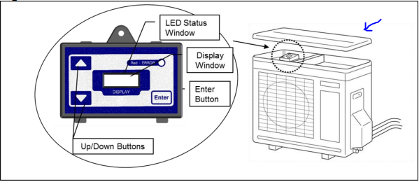
Once you have access to the clock control unit you can set the block out (BO) timer by following the steps below, this will allow you to set your block out hours.
1 - Hold down "UP" and "DOWN" together - gets you to "HSE" mode
2 - Press "UP" - gets you to outlet water temp setting mode
3 - Press "UP" - gets you to BO mode
4 - Press "ENTER" - gets you to EDIT BO mode (then enter the hours accordingly).
For more information consult page (17-22) of your Sanden installation manual which can be found here.
Setting the hours you want to block out
The block out time functions using four digits first two digits = off, second two digits = on so:
To set the timer to run between 12 midday (AEST) and 6 pm set the blackout timer to 1812, which means off at 6 pm (18 in 24 hr clock terms) and on at 12 pm.
To set the black out timer to run off-peak you might choose 0722 which means on at 10 pm (in 24 hr notation) and off at 7 am. Ensure that the off-peak tariff supplies a minimum of 5 hours continuous power to the Sanden HPHW.
If in doubt don't hesitate to contact us at info@pure-electric.com.au and we can guide you through the process
- What are the benefits of rooftop solar power?
There are many benefits in installing a solar PV system including:
- Reduce or eliminate your power bill - you can regain control of your electricity costs.
- A revenue generating asset - you make back many times the initial cost of the system over the lifetime of your solar PV system.
- Add value to your home - a solar system adds value to your home increasing the resale value.
- Reduce your carbon footprint - a solar system generates no greenhouse gases while in operation giving you zero carbon power and lowing your overall carbon footprint.
- Reduce or eliminate your power bill - you can regain control of your electricity costs.
- How do I connect my Fronius SnapINverter to Wifi?
Need help setting up WiFi for your Fronius SnapINverter (Fronius Primo / Fronius Symo) to your Fronius Solar.web monitoring?
Have you recently changed your WiFi network's password, WiFi modem, internet service provider or shifted to NBN? If so, you will need to update your WiFi password settings otherwise you will not be able to view your Fronius solar PV system online in the Fronius Solar.web monitoring portal and might recieve an email to your registered Fronius Solar.web accounts reporting fault 996 - communicatoin error between inverter and Solar.web.
Below are steps for how to set up / change your WiFi details.
Step 1 - Activate WiFi Access Point
- Go the Fronius SnapINverter front screen, scroll until you see the "SETUP" sub menu - this will look like a spanner and a screwdriver and press ENTER (fourth button on the right)
- Scroll down to the second menu option, "WiFi Access Point", press ENTER (fourth button on the right)
Step 2 - Connect Fronius SnapINverter to your Smart Device (e.g. Tablet / Phone)
- Go to your Smart Device (e.g. Tablet / Phone) - click WiFi and look up and select the Fronius WiFi Access Point - this will look something like "FRONIUS_240.XXXX" so you can connect to the inverter
- Enter the Password: 12345678 and now your Smart Device should be connected to the Fronius inverter
Step 3 - Connect Fronius SnapINverter to your Home WiFi Network
- Open up a webpage on your browser and enter the IP address: 192.168.250.181
- Click the 'Settings' cog
- Now the Fronius inverter page should show up. On the left hand side of the page you'll see various tabs. To change the WiFi settings go to the NETWORK tab.
- Go to WLAN Settings, select your WiFi network and click SET
- Enter your WiFi Home Network Password and press SAVE
- On the button below the list of WiFi Networks - Press CONFIGURE WLAN IP and check that it is set to Dynamic. If so Press Ok
- At the top press the TICK Button to Save
Step 4 - Check that the settings are saved
- Activate the WiFi Access Point and connect your inverter to the Smart Device (as per steps aboe)
- When you see the Fronius inverter settings screen - click "SYSTEM INFORMATION"
- Look for LED states and check that the Globe symbol is GREEN
- How to reset customer password for Fronius GEN24
When your Fronius GEN24 inverter has been installed, you'll have a customer password provided at install. Sometimes if there is an issue or you have forgotten the password provided, you might need to re-set it. That's ok and this guide will help you re-set your Customer password.
If you've forgotten the password for the local user interface of the inverter, click on "Forgot password?" to generate a PIN for the relevant user role ("Customer" or "Technician"). This PIN can be used to create a recovery key, allowing you to reset the respective password.
To reset the "Customer" password for a GEN24 inverter, log in to your system on Fronius Solar.web using the generated PIN. Navigate to "Settings" --> "Components," and click on "Actions" for the data source linked to the inverter. Use the "Reset Customer Password" function to generate a recovery key for your new "Customer" password. Please note that only the owner of the Solar.web system can access the "Reset Customer Password" function.
If you don’t see this function, it indicates that you are not set as the system owner. In this case, please contact your system installer. The "Technician" password can only be reset through a recovery key created by Fronius Tech Support.
Resetting the "Technician" password is restricted to trained specialist personnel (electrician, system installer, or Fronius System Partner). To reset the "Technician" password, contact your system installer.
Please note that the recovery key is only valid while the corresponding PIN is displayed on the inverter's user interface after clicking "Forgot password?". If the inverter is restarted or if the recovery key is entered incorrectly five times, a new PIN will be generated. In such cases, a new recovery key must also be created.
Here's a quick How-to video to Reset GEN24/Tauro Customer Password via Solar.web
- I have single phase power, how much rooftop solar PV can I install on my roof?
If your house is single phase power, the amount of rooftop solar PV that you can install will depend on your electricity network provider, as each electricity network provider has different rules.
In almost all instances, you can install more inverter capacity than what the electricity network provider says, so long as you grid export limit your solar PV system. Note: Not all inverters have grid export limit capability.
Below is a table showing the allowed capacity (inverter capacity and your grid export limit), for each of the electricity network providers for single phase households:
SA Power Networks (SA) max 10kW inverter capacity, 5kW export limit Powercor (VIC) no inverter limit, 5kW export limit CitiPower (VIC) no inverter limit, 5kW export limit Ausnet Services (VIC) max 10kW inverter capacity, 5kW export limit United Energy (VIC) max 10kW inverter capacity, 10kW export limit Jemena (VIC) max 10kW inverter capacity, 10kW export limit Energex (QLD) max 10kW inverter capacity, 5kW export limit Ausgrid (NSW) max 10kW inverter capacity, 10kW export limit EVO Energy (ACT) max 10kW inverter capacity, 5kW export limit - What rebates can I get with my rooftop solar system? And how much are they worth?
Solar rebates come in three forms:
- Federal rebates: i.e. Small-scale Technology Certificates (STC) which are available in all states.
- State based rebates: Available in some states from time to time and may be means tested (you can email info@pure-electric.com.au for more details).
- Feed in tariffs: Different tariffs are offered by different retailers.
Small-Scale Technology Certificate (STC) rebate
Currently, all solar systems are eligible for an STC rebate which is calculated using four factors.
Factor 1: The total size of your system in kW
i.e. you have a 10 kW of panels and an 8.2 kW inverter your system size is considered 10 kW
Factor 2: The Zone you are in
Australia is divided into four solar zones.
Zone Rating 1 1.622 2 1.536 3 1.382 4 1.185 To find out which zone your postcode is in click this link.
Factor 3: The STC multiplier based on the year in which you install your solar system
The STC multiplier is a factor worked out based on what year you install your solar system and is as follows:
Factor 4: The price of STCs
STCs can be priced through the Government's STC clearing house or on the open market at places like Green Energy Markets.
As an example say that you are installing 10 kW of panels, in Zone 1 in 2020 and the current price of an STC is $35 your STC rebate would then be:
STC rebate = 10 x 1.622 x 11 x 35 = $6,244.70
This would appear as a $6,244.70 discount off the total cost of your solar system.
State specific rebates and Feed in Tariffs (FiT)
If you want to find out the currently available up-front rebates or Feed in Tarrifs (i.e. the amount you are paid for feeding power back into the grid) you can always email us at info@pure-electric.com.au for more details.
The following is a list of state government entities that manage state based solar incentive schemes:
- VIC - See the following website: https://www.solar.vic.gov.au
- SA - See the following website: https://www.sa.gov.au/topics/energy-and-environment/energy-efficient-home-design/solar-photovoltaic-systems
- WA - See the following website: https://www.wa.gov.au/organisation/energy-policy-wa/energy-buyback-schemes
- QLD - See the following website: https://www.qld.gov.au/housing/buying-owning-home/energy-water-home/solar
- ACT - See the following website: https://www.actsmart.act.gov.au/energy-saving/rebatessubsidies
- NSW - See the following website: https://energysaver.nsw.gov.au/households/solar-and-battery-power
- Federal rebates: i.e. Small-scale Technology Certificates (STC) which are available in all states.
- How do I connect my Fronius GEN24 Inverter to WiFi? (No WPS Option)
Need help setting up WiFi for your Fronius GEN24 Inverter to your Fronius Solar.web monitoring? This method is if you don't have a WPS button on your modem. The WPS method is faster (if available) and we have a separate page for that.
Have you recently changed your WiFi network's password, WiFi modem, internet service provider or shifted to NBN? If so, you will need to update your WiFi password settings otherwise you will not be able to view your Fronius solar PV system online in the Fronius Solar.web monitoring portal and might recieve an email to your registered Fronius Solar.web accounts reportin fault 996 - communicatoin error between inverter and Solar.web.
Below are steps for how to set up / change your WiFi details.
Step 1 - Activate WiFi Access Point on the Fronius GEN24
- Go the Fronius GEN24 Inverter and place your finger over the Optical Button where it shows the Finger icon - only briefly tap your finger ONCE before removing it.
- Just to the right you'll see a blue flashing light - this indicates the WiFi Access Point has been initiated
Step 2 - Connect Fronius GEN24 to your Smart Device (e.g. Tablet / Phone)
- Go to your Smart Device (e.g. Tablet / Phone) - click WiFi and look up and select the Fronius WiFi Access Point - this will look something like "FRONIUS_XXXXXXXX" (the Serial Number of the Inverter) so you can connect to the inverter
- Enter the Password: 12345678 and now your Smart Device should be connected to the Fronius inverter
Step 3 - Connect Fronius GEN24 Inverter to your Home WiFi Network
- Open up a webpage on your browser and enter the IP address: 192.168.250.181
- Now the Fronius GEN24 inverter page should show up showing your Production and Consumption bubbles.
- Click the Top Right corner of the screen which shows the three lines, otherwise known as the 'Hamburger' icon
- Now select, "Communications"
- Log-in as "Customer" User and enter your Password and click "Login". The screen should revert back to the Production and Consumption bubbles
- Click the three lines in the top right corner again, the 'Hamburger' icon and click "NETWORK"
- Now scroll down to Wifi, click your WiFi Network
- Enter your WiFi Home Network Password and press DONE
Step 4 - Check that the settings are saved
- Go back to solarweb.com to your Fronius PV system and you should see that your monitoring is back up and running