Enphase IQ8AC 360W Microinverter Datasheet
Description
| INPUT DATA (DC) | UNITS | IQ8AC-72-M-INT | IQ8HC-72-M-INT | |||
| Typical module compatibility | - | - | 54-cell/108-half-cell, 60-cell/120-half-cell, 66-cell/132-half-cell, 72-cell/144-half-cell No enforced DC/AC ratio and the maximum input power. Modules can be paired as long as the maximum input voltage is not exceeded and the maximum input current of the inverter at the lowest and highest temperatures is respected. See the module compatibility calculator at: https://enphase.com/en-au/installers/microinverters/calculator. | |||
Minimum/Maximum input voltage | Udc,min/Udc,max | V | 18/60 | |||
Start-up input voltage | Udc,start | V | 22 | |||
Rated input voltage | Udc,r | V | 36.5 | 37.0 | ||
Minimum/Maximum MPP voltage | Umpp,min/Umpp,max | V | 28/45 | 29.5/45 | ||
Minimum/Maximum operating voltage | Uop,min/Uop,max | V | 18/58 | |||
Maximum input current | ldc,max | A | 14 | |||
Maximum short-circuit DC input current | Isc,max | A | Maximum short-circuit current for modules (Isc) allowed being paired with IQ8 Series Microinverters: 20 A (calculated with 1.25 safety factor as per IEC 62548). | |||
Maximum input power (Installer should not exceed the small-scale technology certificate (STC) limit on PV module wattage for claiming the STC. Pairing PV modules with wattage above the limit may result in additional clipping losses. See the compatibility calculator at https://enphase.com/en-au/installers/microinverters/calculator.) | Pdc,max | W | 480 | 505 | ||
OUTPUT DATA (AC) | UNITS | IQ8AC-72-M-INT | IQ8HC-72-M-INT | |||
Maximum apparent power | Sac,max | VA | 366 | 384 | ||
Rated apparent power | Pac,r | VA | 360 | 380 | ||
Nominal grid voltage | Uac,nom | V | 230 | |||
Minimum/Maximum grid voltage | Uac,min/Uac,max | V | 184/276 | |||
Rated/Maximum output current | lac,max | A | 1.57/1.59 | 1.65/1.67 | ||
Nominal frequency | fnom | Hz | 50 | |||
Minimum/Maximum frequency | fmin/fmax | Hz | 45/55 | |||
Maximum units per single-phase 20 A circuit | - | - | 11 (L+N) Single-phase | 39 (3L+N) Multi-phase | 10 (L+N) Single-phase | 36 (3L+N) Multi-phase |
Maximum units per multi-phase 25 A circuit | For IQ Cable with 2.5 mm2 stranded conductors and using a 1.20 safety factor. The safety factors applied may vary based on local regulations or best practices, as well as upon the characteristics the OCPD selected. | |||||
Recommended maximum units per single/multi-phase IQ Cable section to reduce voltage rise in IQ Cable | - | - | 8 (L+N) Single-phase | 18 (3L+N) Multi-phase | 8 (L+N) Single-phase | 18 (3L+N) Multi-phase |
It is recommended to center feed the IQ Cable within microinverter branch circuits to minimize the voltage rise. These design limits should ensure voltage rise and line conductor resistance on the IQ Cable are maintained within acceptable limits. In locations with a risk of high grid voltage at the point of connection, it may be necessary to decrease the maximum number of microinverters on the IQ Cable section by as much as 50%. | ||||||
Protective class (all ports) | - | - | II | |||
Total harmonic distortion | - | % | <5 | |||
Power factor setting | - | - | 1.0 | |||
Power factor range | cos phi | - | 0.8 leading ... 0.8 lagging | |||
Inverter maximum efficiency | ηmax | % | 97.3 | 97.4 | ||
European weighted efficiency | ηEU | % | 96.6 | 96.8 | ||
Inverter topology | - | - | Isolated (HF Transformer) | |||
Nighttime power loss | - | mW | 50 | |||
MECHANICAL DATA | UNITS | IQ8AC-72-M-INT | IQ8HC-72-M-INT | |||
Ambient air temperature range | °C (°F) | -40 to 60 (-40 to 140) | ||||
Relative humidity range | % | 4 to 100 (condensing) | ||||
Overvoltage class AC port/DC port | - | III/II | ||||
Number of input DC connectors (pairs) per single MPP-tracker | - | 1 | ||||
AC connector type | - | IQ Cabling (refer to the IQ Cable and accessories data sheet) | ||||
DC connector type | - | Stäubli MC4 | ||||
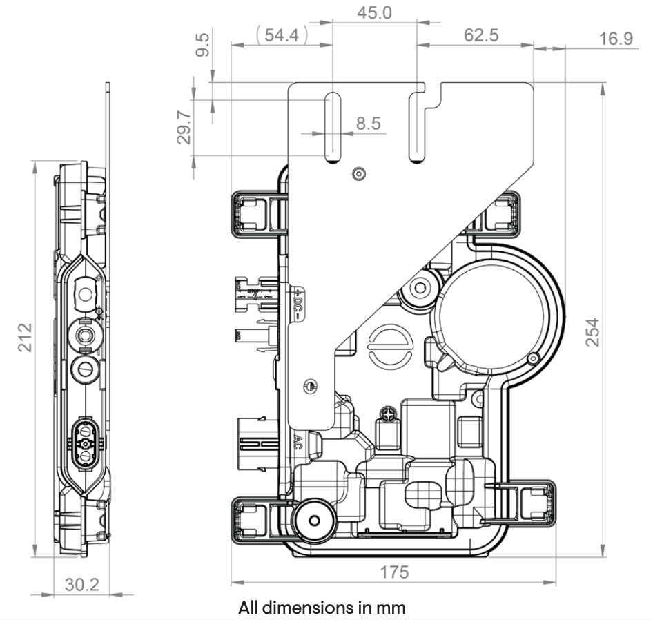
Dimensions (H × W × D) | mm (in) | 212 (8.3) × 175 (6.9) × 30.2 (1.2) (without mounting brackets) | ||||
Weight (with mounting plate) | kg (lb) | 1.1 (2.4) | ||||
Cooling | - | Natural convection – no fans | ||||
Enclosure | - | Class II double-insulated, corrosion-resistant polymeric enclosure | ||||
IP rating | - | Outdoor - IP67 | ||||
Altitude | m | <2,600 | ||||
Calorific value | MJ/unit | 37.5 | ||||
STANDARDS | IQ8AC-72-M-INT | IQ8HC-72-M-INT | ||||
Grid compliance (with IQ Relay) | AS/NZS 4777-2:2020 | |||||
Safety | EN IEC 62109-1, EN IEC 62109-2 | |||||
EMC | EN IEC 61000-3-2, 61000-3-3, 61000-6-2, 61000-6-3, EN IEC 50065-1, 50065-2-1, EN55011 (At STC within MPP range.) | |||||
Product labelling | CE, RCM | |||||
Advanced grid functions (Some of these functions require IQ Gateway Metered with current transformers and/or IQ Relay installed.) | Power export limiting (PEL), phase imbalance management (PIM), loss of phase detection (LOP), power factor control Q (U), cos (phi) (P) | |||||
Microinverter communication | Power line communication (PLC) 110–120 kHz (Class B), Narrowband 200 Hz | |||||