-
What are RECs and STCs, what are they worth? And how many do you get with your Sanden?
What are STCs and how many do you get with your Sanden?
The purchase and installation of a Sanden Eco® Plus Hot Water Heat Pump entitles you to Small-scale Technology Certificates (STCs) – formerly known as Renewable Energy Certificates (RECs). For more information: visit www.environment.gov.au/climate-change and www.cleanenergyregulator.gov.au
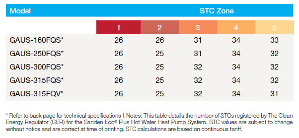
The Sanden HWHP achieves the highest level of STCs of any hot water heat pump, currently available in Australia, and these are as below:
To find out which zone your postcode is in click here (note this may change so if in doubt contact the clean energy regulator for more information)
The Table below shows how many STCs are available for each Sanden model in each STC Zone
How much are STCs worth?
STCs can be priced through the Government's STC clearing house or on the open market at places like Green Energy Markets.
So say you bought a Sanden GAUS-250FQS and you lived in zone 4 and the current STC price was $35
The total discount you would receive would be: 34 STCs x $35 = $1,190.
So you would receive a discount of $1,190 off the total price of your Sanden unit (note this is an example only to illustrate how STCs are calculated the actual discount will vary depending on the current STC price).
-
Sanden Wi-Fi Controller Reset
You have a Sanden Wi-Fi controller with model Wi-Fi-HPD for your Sanden Eco Heat Pump Model GAU-A45HPD and you're finding you can't add the Wi-Fi controller when tapping "Add Device"? Read on below.
Some symptoms reported by clients are:
- Wi-Fi Controller shows connectivity, but cannot change settings
- Heat Pump Status remains on Standby
- Wi-Fi status lights are correct but cannot find the Wi-Fi controller when tapping “Add Device”.
Actions:
- Check that Communication setting mode, C_SE is set to onHP on internal, Smart Controller
- Remove front cover of Wi-Fi controller, using a Phillips head screwdriver.
NB: Do not use a screw gun / drill as you will overtighten the screws when re-installing
- Identify “SW1” and flick the 4th switch position to the opposite side. (You do not need to flick it back).
- LED display will be Red/Blue/Red
- Open the Smart Life App and tap “+” top right corner,then tap “Add Device”:
- App will search for devices, displays the Heat Pump under the “Discovering devices” heading. Tap “Add”.
- Enter Wi-Fi Uername and Password, then tap “Next”
- App will confirm device being added, then tap “Done”.
- LED display will be Red/Blue/Green
You can also check out our page PDF page here which includes screenshots -> https://pure-electric.com.au/resources/sanden-wi-fi-controller-reset-wi-fi
-
What are the benefits of the Sanden Eco® Plus heat pump hot water system?
Benefits include:
You can save up to 80% of your hot water energy costs when compared with a traditional electric hot water system! The Sanden Eco® Plus Hot Water Heat Pump uses only 20% of the energy required by older-style, electric element hot water storage systems.
Not only does a Sanden Eco® Plus heat pump hot water system help save on energy costs, it also delivers:
(a) Heat Pump Unit Benefits:
- Innovative technology; up to 50% faster heat recovery than currently available Hot Water Heat Pumps.
- Industry leading quality & performance; the Sanden Eco Plus gives you the highest level of STC credits of any currently available heat pump hot water system.
- Class leading warranties; backed by Sanden’s 35 years of operation in Australia.
(b) Stainless Steel Storage Tank Benefits:
- High quality; extra long life duplex stainless steel cylinder.
- Fully insulated; for extremely low heat loss.
- Safety, pressure and temperature relief valves.
- Mains pressure rated.
- Innovative technology; up to 50% faster heat recovery than currently available Hot Water Heat Pumps.
-
Is water quality an important consideration for the Sanden Eco® Plus heat pump hot water system?
Yes, importantly no warranty applies to the heat pump unit and the storage tank, where the chloride level exceeds 200 mg/litre and the pH is less than 6.0. If in doubt, seek water quality information from your local council or water supplier.
-
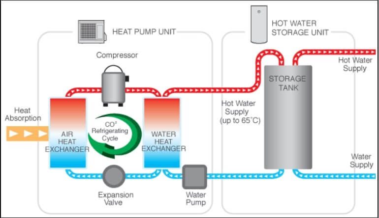
How does a heat pump hot water (HPHW) system work?
The Sanden Eco® Plus heat pump hot water (HPHW) system operates like a refrigerator in reverse. It contains a fan that forces air through an evaporator that contains a refrigerant. The heat in the ambient air passes through the evaporator (note: even air below 0 º C contains heat energy) and is absorbed by a natural refrigerant, R744 (aka CO2), which is ozone friendly and does not significantly contribute to global warming compared with most other refrigerants (older style refrigerants have thousands of times more global warming impact for the same amount of gas, when compared with CO2).
The warm gaseous refrigerant is circulated in the system via a compressor. As it passes through the compressor, its pressure rises, as does its temperature. This hot refrigerant then passes through a heat exchanger to heat the water, which is finally pumped to the storage tank.
-
What do I do if the Sanden Eco® Plus heat pump hot water system has a problem?
Check our comprehensive Sanden not working checklist here if you think you have a problem with your Sanden Eco heat pump hot water system.
If you're still unsure after going through this guide - please lodge a Pure Electric Service Case here
-
Error Codes for Sanden Heat Pump G4 GAU-A45HPC
The HP will display an error code if it is unable to function normally.
Error codes are indicated by a red LED on the control panel. The control panel is visible via a small window at the right side of the heat pump and it can be accessed by removing the heat pump top cover (4 screws).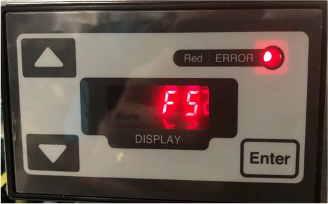
After a component is replaced or the inspection is completed, cycle power to the unit several times to confirm the error does not re-occur.
Below is the list of the error codes. If the corrective action does not solve the error problem, a malfunction of the PCB valve is highly likely.Error
code
Reason for the error
Corrective action
H9
HP ambient(outdoor)
temperature thermistor error
Check the thermistor connectors on the main PCB or control PCB in the heat pump unit for any disconnection, fall-off, wire breakage or short circuit.
Measure resistance of the thermistor indicated by the error code.
HC
HPwater outlet (outgoing)
temperature thermistor error
J3
HP discharge temperature
thermistor error
J5
HP suctiontemperature
thermistor error
J6
HP defrosttemperature
thermistor error
J8
HPwater inlet (return)
temperature thermistor error
H7
Tank temperature thermistor error
- Check the thermistor cable on the terminal block in the heat pump unit for any disconnection, fall-off, wire breakage or short circuit.
- Measure resistance of the thermistor indicated by the error code.
E6
Compressor bootingerror
- Check the compressor connector.
- Replace the main PCB or heat pump.
H6
Compressor revolution error
- Check the supply voltage.
- Measure resistance of each thermistor.
- Measure resistance of coil of expansion valve to check open or short circuit.
Error
code
Reason for the error
Corrective action
Replace the PCB or heat pump.
U0
Refrigerant leakageerror
- Measure resistance of each thermistor.
- Measure resistance of coil of expansion valve to check open or short circuit.
- Replace the main PCB or heat pump.
E1
Main PCB error
Replace the control PCB.
E2
L7
Control PCB error
Replace the control PCB.
F5
Communication error between main PCB to control PCB
- Check the communication connector on the main PCB and control PCB.
- Replace the main PCB or control PCB.
E8
High inlet current error
- Check the installation location.
- Check the supply voltage.
- Replace the main PCB or heat pump.
H8
Current error
Replace the main PCB.
L4
High temperature of module error
- Check the installation location.
- Remove foreign objects from the evaporator coil (e.g. fallen leaves, grass, snow).
- Check the fan motor is not flowing by dirt.
- Replace the main PCB or fan motor.
L5
High outlet current error
- Measure resistance of the discharged thermistor.
- Measure resistance of coil of expansion valve to check open or short circuit.
- Replace the main PCB or heat pump.
P4
Module temperature
thermistor error
Replace the main PCB.
U2
High voltage error
Check the supply voltage.
HJ
Water circuit error
- Check the inlet water valve.
- Check for any piping bend, blockage, kink or frozen.
- Measure resistance of each thermistor.
- Measure resistance of coil of expansion valve to check open or short circuit.
- Replace the main PCB or heat pump.
EC
High water outlet error
- Check the water circuit is not flowing by air, dirt or scaling.
- If the water circulation pump is not working, replace the pump.
- Measure resistance of water outlet (outgoing) thermistor.
- Replace the main PCB.
E9
Water circulation pump error
- Check the water is full in the tank.
- If the water circulation pump is not working, replace the pump.
- Check the revolution of pump by controller. If the revolution is low, replace the pump.
- Replace the main PCB.
Error
code
Reason for the error
Corrective action
E7
Fan motor locked
- Remove foreign objects around the fan motor.
- Check the fan motor connectors on the main PCB.
- Replace the main PCB.
F3
Discharged temperature error
- Measure resistance of the discharged thermistor.
- Replace the main PCB or heat pump.
Error
code
Reason for the error
Corrective action
H9
HP ambient(outdoor)
temperature thermistor error
Check the thermistor connectors on the main PCB or control PCB in the heat pump unit for any disconnection, fall-off, wire breakage or short circuit.
Measure resistance of the thermistor indicated by the error code.
HC
HPwater outlet (outgoing)
temperature thermistor error
J3
HP discharge temperature
thermistor error
J5
HP suctiontemperature
thermistor error
J6
HP defrosttemperature
thermistor error
J8
HPwater inlet (return)
temperature thermistor error
H7
Tank temperature thermistor error
- Check the thermistor cable on the terminal block in the heat pump unit for any disconnection, fall-off, wire breakage or short circuit.
- Measure resistance of the thermistor indicated by the error code.
E6
Compressor bootingerror
- Check the compressor connector.
- Replace the main PCB or heat pump.
H6
Compressor revolution error
- Check the supply voltage.
- Measure resistance of each thermistor.
- Measure resistance of coil of expansion valve to check open or short circuit.
Error
code
Reason for the error
Corrective action
Replace the PCB or heat pump.
U0
Refrigerant leakageerror
- Measure resistance of each thermistor.
- Measure resistance of coil of expansion valve to check open or short circuit.
- Replace the main PCB or heat pump.
E1
Main PCB error
Replace the main PCB.
E2
L7
Control PCB error
Replace the control PCB.
F5
Communication error between main PCB to control PCB
- Check the communication connector on the main PCB and control PCB.
- Replace the main PCB or control PCB.
E8
High inlet current error
- Check the installation location.
- Check the supply voltage.
- Replace the main PCB or heat pump.
H8
Current error
Replace the main PCB.
L4
High temperature of module error
- Check the installation location.
- Remove foreign objects from the evaporator coil (e.g. fallen leaves, grass, snow).
- Check the fan motor is not flowing by dirt.
- Replace the main PCB or fan motor.
L5
High outlet current error
- Measure resistance of the discharged thermistor.
- Measure resistance of coil of expansion valve to check open or short circuit.
- Replace the main PCB or heat pump.
P4
Module temperature
thermistor error
Replace the main PCB.
U2
High voltage error
Check the supply voltage.
HJ
Water circuit error
- Check the inlet water valve.
- Check for any piping bend, blockage, kink or frozen.
- Measure resistance of each thermistor.
- Measure resistance of coil of expansion valve to check open or short circuit.
- Replace the main PCB or heat pump.
EC
High water outlet error
- Check the water circuit is not flowing by air, dirt or scaling.
- If the water circulation pump is not working, replace the pump.
- Measure resistance of water outlet (outgoing) thermistor.
- Replace the main PCB.
E9
Water circulation pump error
- Check the water is full in the tank.
- If the water circulation pump is not working, replace the pump.
- Check the revolution of pump by controller. If the revolution is low, replace the pump.
- Replace the main PCB.
Error
code
Reason for the error
Corrective action
E7
Fan motor locked
- Remove foreign objects around the fan motor.
- Check the fan motor connectors on the main PCB.
- Replace the main PCB.
F3
Discharged temperature error
- Measure resistance of the discharged thermistor.
- Replace the main PCB or heat pump.
-
The cold water valve (or ECV) on my Sanden is leaking a lot what is causing this?
To answer the question why is my cold water valve (or ECV) on my Sanden leaking a lot what is causing this? A few elements to consider.
To protect your Sanden unit from excessive pressure there are three valves:
Valve 1. The pressure reduction valve (PRV) which is located on the water inlet to your home and is set to 500kPa. This valve is designed to keep the pressure out of any tap in your house below 500 kPa.
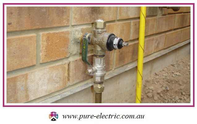
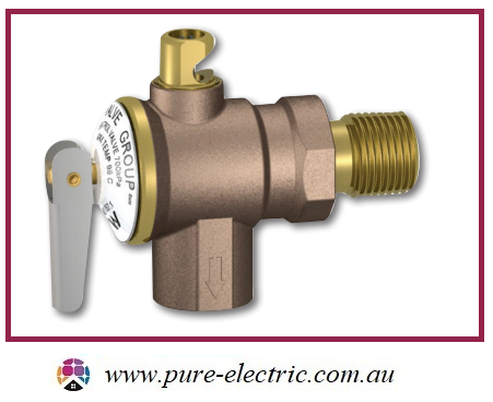
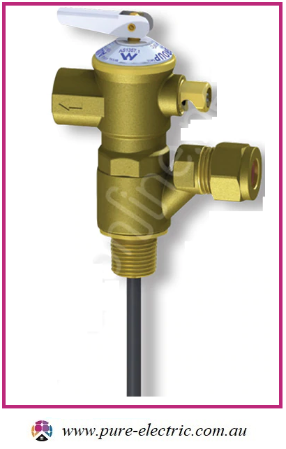
Valve 2. The expansion control valve (ECV) which is located on the cold water inlet to your Sanden and is set to 600 kPa. This valve is designed to relieve cold water instead of hot water during the heating cycle (which increases pressure in the tank) which saves you money and protects the final valve, the PTR.
Valve 3. The Pressure and temperature relief valve (PTR) which is located on the hot water outlet to the Sanden and is set to 700 kPa. This valve is designed to release hot water from your tank if the pressure gets too high or the water heating cut-off fails to work.
One of the main reasons ECV valves leak water excessively (apart from wear and tear or malfunction) is excessive water pressure in the mains supply which is not properly being reduced by a PRV as it enters your house to at or below 500 kPa; in many areas the mains water pressure is 850 kPa + this is to ensure fire fighters have enough pressure to use their fire hoses properly in the event of a fire.
Note: the Australian standard covering water pressure in the home (AS 3500.1:2018) mandates that water pressure in your home must be kept below 500 kPa as water pressure above 500 kPa has the potential to damage valves, tap fittings, flexible hose fitting etc as the components are only rated to withstand pressures at or below 500 kPa.
So if you notice that the expansion control valve (valve 2 discussed earlier) on your Sanden is leaking excessively chances are you have excessive water pressure at your house and your PRV (valve 1) is either not present or not working.
Either way you should get a plumber to check the water pressure in your house and make sure you have a functional PRV. You can also buy a cheap pressure meter from a hardware shop if you want to check your household water pressure yourself: Note your mains pressure is not constant it will change based on a number of factors including local water use, time of day, time of year or changes in your local area such as new housing being built etc.
-
Sanden Heat Pump Hot Water Not Working
If you believe your Sanden Eco Heat Pump is not producing hot water, please try the following:
- Unless there is water pouring (not dripping) out of the unit, do not turn the unit off and on until you've checked the clock / control panel for an error message (under our "Resources" section you can find the different error code pages to help you determine what an error code looks like). If water is pouring out then turn the unit off at the isolator and at the switchboard that circuit is attached to.
- Pull the PTR Valve on the Tank - this confirms if there is hot water in the tank. If unsure about the water temperature use a thermometer. If water is cold goto (2) If there is 50C or so hot water in the tank then the problem is not the heat pump system) the problem is on the house side of the tank. So the tempering valve needs to be checked for a blockage / choke, if it is installed upside down or if it has failed (they are consumable items with a lifespan of 5-6 years and they fail to safe when they fail meaning cold water).
- Check the electricity supply - Confirm/check both (1) circuit breaker at the switchboard is ON + (2) Isolator at the HP unit is ON
- If you see a little Red Dot in the bottom right corner, then the HP unit has power connected. For the older G2 model 2010-2016 the dot is on the controller hidden under the lid - you will need a screwdriver to remove the 4 screws from the each end of the lid.
- Check if there are any Error Codes at the clock/computer control panel. If an error code is present, take note of the Error Code. Turn off the HP at the isolator (wait 1 minute) and turn on the HP again to see if the Error Code re-appears. The unit is functioning correctly if it blows cold air for more than 30minutes. NOTE: The unit takes about 7 minutes to start blowing cold air after power is applied.
- If system is newly installed or new plumbing works have occurred on site confirm that the tempering safety valve (valve with orange/yellow cap) is installed the right way up with a H on the vertical barrel above the adjustable valve and a C below the adjustable valve. If the system is more than 5 years old please note these valves officially only have a minimum life span of 5 years and may need replacing.
- Air bleed the system - Open the water drain plugs on the right hand side of the HP unit (one at a time for a good 3 minutes PER drain plug, ONE at a time). G4 units have an additional bleed port on the underside of the heat pump - please only turn this 180 degrees approx when opening it up - bleed this for 3 minutes also. Re-set the HP unit at the Isolator.
- Hard re-set the HP unit controller:
- Switch off power to the HP
- With power switched off press and hold down both “Up” and “Down” keys on the control panel simultaneously
- With the keys still pressed switch on power to the unit, the display will show “FClr” .... wait 10 seconds.
- To complete the reset cycle power to the unit off (wait 1 minute) and then on again.
- With power back on the time will be displayed (if required adjust to correct time) and the unit will run it's start up procedure.
- When switching power on again, the country setting "1.AU" may appear on the display. If for any reasons this setting remains on the display, simply press "Enter" and the Control Panel to confirm and HP will continue the start-up process.
- Physical inspection of the HP
- Turn off the electrical isolator, to allow power to discharge, wait 5 minutes after the power is turned off
- Take the top panel off by unscrewing the 4x screws
- Check to see if any debris/foreign objects are the top of the unit
- If an onsite plumber or electrician has a volt meter check for ~230VAC at the terminals on the side of the unit.
- If you have an older G2 unit and E124 is displaying then the unit has been subject to either high grid voltages or has suffered a power spike. Adding a timer to the switchboard and keeping the unit powered off for more than 19 hours per day can clear the fault for each and every use. This is successful in 50% of cases however works better where it is done the first time the error is ever seen. Not where the unit has been turned on and off many times.
- If you are getting E040 on an older G2 unit then you can clean the filter via the filter housing at the bottom of the unit adjacent the air bleed drain plugs. This may get you up and running again temporarily while you book a service. BOOK YOUR SERVICE OPTION HERE
- For blockages in newer units a 3 way ball valve can be installed which allows the consumer to perform their own reverse flush of the system. This maintenance step is normally part of a 4 year service can then be done annually just before the air bleed is performed.
-
Sanden Eco Heat Pump working but running out of hot water?
If you have a Sanden Eco heat pump hot water system that is working but you find you're running out of hot water before your Sanden commences it's daily start up - this is most likely because you have a block out time period not suitable for your hot water load consumption.
Rectification is to change the Bllockout timer setting on your Sanden Eco heat pump (condenser unit) to either of the below Scenarios:
Most likely your current BO Timer is set up with a 5 hour period (e.g. "1611"- 11am to 4pm) - change this to either:
Scenario 1: Amend your Blockout Timer with a longer time period e.g. 0211
Keep the 'start' time of your Blockout Timer the same e.g. 11am to maximise rooftop solar PV production and change the 'end' time to e.g. 2am the next morning.
Your BO time on the control panel should read "0211" in this scenario.
Scenario 2: Disable the Blockout Timer
Find you're still running out of hot water? Disable the blockout timer.
Change the 'start' time of the Blockout Timer to "00" and change the 'end' time of the Blockout Timer to "00"
Your BO time on the control panel should read "0000" in this scenario.
info@pure-electric.com.au
1300 86 78 73